 Your Privacy Choices
If you have a Mosin-Nagant rifle or if you are a member of Internet communities of military surplus firearms, then you’ve probably come across a marksmanship chart (in Russian) for the Mosin-Nagant rifles. It looks to be a very handy reference. Although many of the parts are self-explanatory, there are some sections of this chart that are not easily understandable and cause some confusion because of being written in a foreign language. I’ve been asked multiple times to explain or translate this or that part of the chart. Eventually, I decided to completely translate it because there is an interest and demand for it. Hopefully, this translation will be useful for many firearms enthusiasts and researchers.
This marksmanship chart was drawn in 1947 by a man named Colonel R.P. Oparin. Its purpose is to aid shooting the Mosin-Nagant M91/30 rifles and carbines (M38, M44). Due to shorter barrels, carbines have different ballistics that’s why in the Oparin’s chart, the carbine data is written inside the circles. The chart itself was enclosed in a handbook that explained each of the 16 segments of the chart. Besides the Mosin-Nagant rifle/carbine chart, the handbook also includes another one written for the DP-27/DPM light machine gun. If you understand Russian, you can download that handbook by clicking here.
Below is the scanned copy of the original chart (in Russian) and my translation. In order to get the full resolution images, right click on the images and open them in a separate tab of your browser.

Note, that some of the terms and expressions are not literally translated, but replaced with corresponding expressions in English to make the chart readable and understandable.
Let’s go through each of the sections and see what information they give.
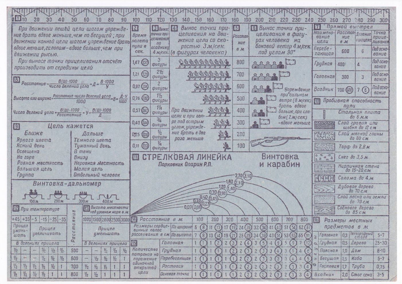
1) Milliradian Ruler

On the very top of the chart, there is a milliradian ruler. Each small increment is equal to 2 Mils. In the handbook, Oparin gives an example of using the ruler. For example, if you need to measure the distance to the turn of the road, you’ll need to place the ruler at 50 centimeters from your eye (average distance of outstretched hand) and measure by how many Mils the road is covered at that distance. Let’s say the road’s width at the needed distance measures 14 Mils. Knowing that the width of that road is 7 meters, you can place those numbers into the following formula and get the distance to the turn of the road.
Distance = Heigh(Width) x 1000 / Mils
In our example, the distance to the turn of the 7 meter wide road that covers 14 mils will be 500 meters (7 x 1000 / 14 = 500).
It’s important to know that the Soviet Mils are slightly different than NATO Mils. Both are rounded for the sake of calculations simplification. Milliradian (or Mil or Mrad) is an angular measurement that is equal to one-thousandth of a radian (one radian is about 57.3 degrees). The NATO Mil is slightly smaller than the true milliradian. It measures 0.982 of the real Mil. The Warsaw Pact/Soviet Mil is a bit more than the real milliradian and measures about 1.047 of real Mil.
2) Bullet Flight Time

This data is used to evaluate the deflection (a.k.a leading the target, a.k.a Kentucky windage, a.k.a hold off) adjustments at various distances when shooting at moving targets. In order to calculate the lead, one must approximately know the speed of the moving target and the distance to it.
Let’s say the target moves at 5 m/s speed and is at 500-meter distance. Using the table, we can see that it takes 0.76 seconds (0.82 seconds for the Mosin-Nagant carbine) for the bullet to reach the 500-meter distance. Then, by multiplying the time of the bullet flight with the speed of the moving target, we’ll find out the needed hold off. In our example, it will be 5 m/s x 0.76 seconds = 3.8 meters of deflection (for the carbine it will be 5 x 0.82 = 4.1 meters). It means you’ll need to have your point of aim 3.8 (4.1) meters ahead of your target in the direction of its movement.
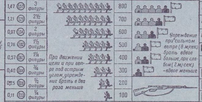
3) Deflection for Cavalry Targets Moving at 4 m/s Speed
This column shows the amount of needed lead in horse silhouettes when shooting at a cavalry target which moves at 4 m/s speed at the distances shown in column 5. This is a simplified method than the calculation using the bullet flight time. In order to determine the lead in horse silhouettes, you need to find the distance at which your target is and see how many silhouettes it corresponds to. For example, if the horseman is at 500 meters, then you need to have your point of aim 1.5 silhouettes in front of it in the direction of its movement. This is, of course, true if the target moves perpendicular to your line of sight and at the mentioned speed.
4) Leading Human Target which Moves at 3 m/s Speed
Using the distance data from column 5, you can estimate the amount of deflection needed to hit the human target moving at 3 m/s speed.
5) Distance Data Column
This column has the distances for estimating the deflection for cases described in columns 2, 3, 4 and 6.
6) Leading a Human Target in Case of 90° Crosswind of 4m/s Speed
This portion is pretty much self-explanatory. The 100 and 200 meter data is replaced by the image of the Mosin-Nagant rifle probably because at these distances the wind of mentioned speed is considered insignificant in terms of affecting the trajectory of the projectile.
7) Point-Blank Range

In his handbook, Oparin says that in some cases there is no time to calculate the distance and holdover to the target. For such situations, you can hit the targets by simply knowing the point-blank ranges of the Mosin-Nagant rifle and carbine for different height targets at certain distances and sight settings. For example, if you are shooting at 400 meters with “4” sight setting and unexpectedly a torso sized target appears at 200 meters, can you hit the closer target without adjusting the sights? The table shows with 4 sight setting you can hit a torso target at any distance up to 400 meters if aiming at the base of the target.
8) Formulas

The three formulas shown in this section will allow calculating the distance to the target (D), target’s height or width (H) and Milliradians (M). By knowing any two of these magnitudes, you can find the third one.
9) Target Size Misperception in Mountainous Terrain

In mountainous terrain, depending on the lighting, color, terrain and location, the objects may seem to be closer or farther. This table gives general information concerning these visual illusions.
The lower portion of this section gives another handy distance estimation method using the amount of human silhouettes fitting the rear sight notch of the rifle.
10) Bullet Penetration
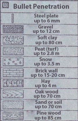
It is really important to know the terminal performance of your firearm/cartridge on different types of barriers. In the handbook, it says that these are for close range shots not specifying the distance.
11) Highest Points of Trajectories.

This chart allows finding the bullet trajectory height at any particular rear sight setting. For example, if you want to know the trajectory height when shooting at 400-meter distance with the proper “4” sight setting, then you need to find the curve that rests on 400 cell in the table below it. Then, see the number written on the curve. In the case of our example, that number is 0.40 (0.45 for the carbine).
This means that the trajectory height will be 0.4 meters or 40 centimeters. It means that when shooting at 400 meters with “4” sight setting, any target of 40 cm height and larger in relation to the line of sight appearing within the 400-meter range will be possible to be hit without any sight adjustments. If the target is less than 40 cm and appears say at 200 meters, then when shooting at that target with “4” sight setting the bullet will fly over the target.
12) Temperature Adjustments

In order to find out the needed sight adjustment at given air temperature, you need to find the distance (in the table) at which you are going to shoot. Then, knowing the temperature find the data in the crossing of distance row and temperature column. For example, if you are shooting at 500-meter distance and the temperature is -15°C (note that the temperature is in Celsius) then the cross of 500-meter row and -15 column will have a 1/2 data meaning that you need to raise the rear sight by half increment.
13) Sight Adjustments in Mountains
Depending on your elevation above the sea level, the air density changes which affects the external ballistics. As a rule, the higher is the elevation of your location the thinner is the air and less resistance it imparts to the projectile. Using the cross cell of the distance row and elevation column, you’ll find how much you need to lower the rear sight.
14) Group Spread Chart

This chart shows the average height and width of spread of the fired groups (in centimeters). As mentioned earlier, the numbers for the Mosin-Nagant carbines are in the circles.
UPDATE: Apparently, these are not the group sizes in modern perception. The numbers show the height or width of a strap drawn over the group of shots that would enclose the 70% of hits. Each strap’s axis must match the center lines of the groups, which divide the hits in half in the horizontal and vertical planes. That being said, “width” numbers are for the vertical straps and height numbers – for the horizontal ones. In the image below the vertical and horizontal straps are highlighted with green and yellow respectively.

15) The Number of Shots Needed to Engage a Given Height Target
This table allows estimating the amount of rounds that is averagely needed to shoot in order to engage a target of given size.
16) Dimensions of Common Objects
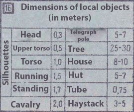
In order to calculate the distances using the formulas in section 8, it is useful to know the approximate dimensions of common objects in your area. This table also contains the information concerning the average human body dimensions.
Interesting to note, that there is no drift adjustment data in the Mosin-Nagant rifle/carbine chart. However, in the LMG chart, there is such section.
I hope you found this article informative and useful. If so, please let me know what other information you would like to see translated into English?
If you find any of the sections not explained well enough, feel free to let us know via e-mail or in the comments section.
Many thanks to Jeffrey Reardon, David Wattles and Aram H. for the idea and assistance in writing this article!